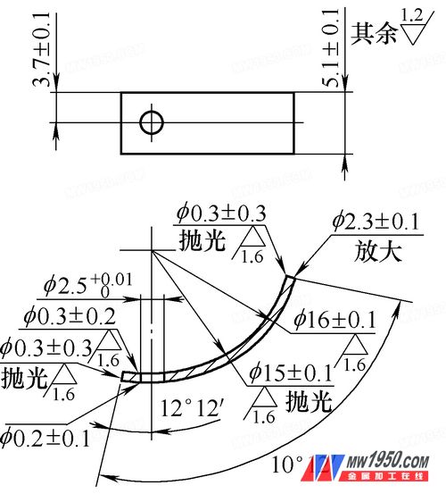
The components are made from custom materials, and each batch of material may vary in quality, consistency, and condition. This variability is a key factor that must be considered during the manufacturing process. Due to changing requirements for use and processing, the design has been modified several times, and the current state is shown in Figure 1.
First, Process Planning
1. Part Structure, Size Characteristics, and Requirements
(1) Part Structure and Size Requirements: The parts are nickel-copper alloy rods with a diameter of φ45mm, no surface treatment or heat treatment is required. The structural dimensions are illustrated in Figure 1.

Figure 1
The part is an annular section, with an inner arc radius of R15 mm ± 0.1 mm, a surface roughness value of Ra = 1.6 μm, and requires polishing. The outer arc has a radius of R16 mm ± 0.1 mm with the same surface roughness requirement. There is a centripetal hole on the arc surface with a diameter of φ2.5 +0.02 0 mm. The inner arc has a rounded corner with R = 0.3 mm, and the outer arc interface has a chamfer of C0.2 mm. The positioning dimension for the φ2.5 mm hole is (3.7 ± 0.1) mm, and the angular dimension is 12° ± 2°. It should be noted that during processing, the core portion with a diameter of φ15 mm must be removed and cannot be used for further part processing.
2. Mechanical Processing Technology Analysis
(1) Part Analysis: Based on the design requirements, the following factors need to be considered during process design and manufacturing: 1) The nickel-copper alloy used for the parts is only available as a φ45 mm bar, with an initial hardness of HRC ≥ 38, which makes cutting difficult. 2) The central core portion of the material with a diameter of φ15 mm cannot be used for part processing, requiring special measures. 3) The part structure is simple and symmetrical, forming a rotating body. The maximum material utilization rate under restricted conditions should be analyzed and calculated in detail. 4) The part is a rotating body with a thickness ranging from 0.8 to 1.2 mm. Machining a φ2.5 mm hole on the arc surface presents challenges in clamping and measuring the angular dimension of the positioning hole. 5) All areas of the R15 mm ± 0.1 mm arc surface require polishing, which necessitates additional auxiliary methods.
(2) Solution: Based on the above analysis and considering the existing production resources and machining methods, the following solutions are proposed: 1) Due to the high material hardness, appropriate tools should be selected for processing. Since the material is conductive, non-hardness-dependent methods such as wire cutting or electric discharge machining can be used. 2) For the machining of the φ2.5 +0.02 0 mm centripetal hole on the arc surface, general milling, numerical control milling, or fitter machining can be used. However, all three methods require tooling, and angular positioning is necessary for hole machining. General milling is inefficient, while numerical control milling involves frequent tool changes, reducing efficiency. With reliable tooling, fitter machining becomes the optimal method. 3) For the polishing process, there are no strict size or precision requirements. Two methods can be used: manual sandpaper polishing by the fitter, or placing the parts and abrasives in a sealed container in a specific ratio to allow relative motion for polishing.
Second, Tooling Design and Usage
Tooling Design
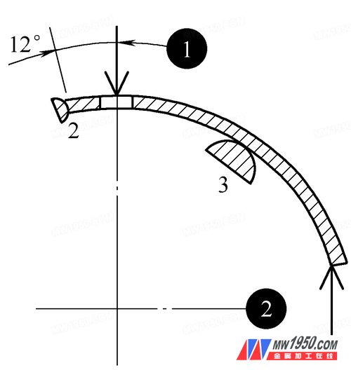
(1) Positioning Analysis and Tooling Requirements: As shown in Figure 1, the centripetal hole φ2.5 +0.02 0 mm has high precision, and one-time drilling by the fitter may not meet the accuracy requirement, so reaming is necessary.
During the machining of the parts, the choice of positioning reference directly affects the positioning accuracy, influencing both processing efficiency and the qualification rate of the parts. According to the principle of selecting the positioning reference, it should be as close as possible to the design basis to reduce or eliminate positioning reference errors, thus minimizing positioning errors. There are two options for machining the φ2.5 +0.02 0 mm holes. The analysis is as follows:

Centrifuge,Centrifuge Machine,Nuclear Centrifuge,Centrifuge Rotor
Zenith Lab (Jiangsu) Co.,Ltd , https://www.zenithlabo.com
