
2.3 Configuring the development environment
Create a secondary development folder under the UG root directory ${UGII_BASE_DIR}, such as USER, create folders startup, application and udo[5] in this folder, and put DR.dlg under application, DR.dll And DR.men is placed under startup, udo is used to store the dynamic link library. Remove the "#" before the #UGII_USER_DIR=${HOME} statement in the UG environment variable file ugii_env.dat to make the statement valid, and change ${HOME} to ${UGII_BASE_DIR}USER.
Add the following system environment variables:
Variable name: UGII_CUSTOM_DIRECTORY_FILE
Variable value: ${UGII_BASE_DIR}USER
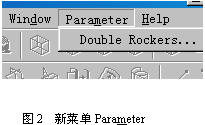
After starting the UG after completing the above tasks, a new menu Parameter will be added before the menu menu in the menu bar, as shown in Figure 2.
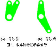
A pair of rocker arm characteristic parameters are modified with reference to Fig. 1. The result is shown in Fig. 3, in which the new value of the feature parameter angle0 is 150 degrees.
3 Virtual Assembly Automation
UG uses the virtual assembly mode of "building assembly using component link relationships." This mode examines the static interference of the target assembly itself, mimics the assembly process of the product, defines the disassembly path, and simulates the motion of the mechanism, analyzes the motion performance of the mechanism, and analyzes the assemblability of the product and its assembly components, and measures the assembly design. The quality of the stage product design results [6]. The above functions can only be realized in the human-computer interaction mode. When the target assembly is a large-scale complex system, there are many deficiencies such as cumbersome operation process, operator fatigue and poor repeatability. In response to this situation, a virtual assembly automation solution is proposed, which is described as follows:
The target orientation of the component in the assembly drawing is input from the file reading or custom interface, and the coordinate conversion of the assembly orientation reference information (coordinate matrix) is performed by the assembly program to realize automatic coordinate positioning of the component. The high-intensity human-computer interaction operation is an imperative operation, which makes the repeated and cumbersome manual operation programmatic, thereby automatically completing the virtual assembly and achieving the purpose of improving production efficiency.
In order to carry out the follow-up work such as dynamic and static interference check after the assembly of the aircraft control system, it is necessary to identify the part event and make it a node after each component is linked and the part occurrences are imported.
The automated process of manipulating the system virtual assembly is as follows:
Assemble() //Virtual Assembly Automation {
Obtaining orientation reference information for assembly of pre-assembled components;
Obtain the orientation of the component in the assembly drawing;
Link components, import widget events;
Spatial orientation conversion;
Identify the part event to make it a node;
};
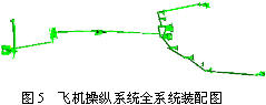
The typical component assembly drawing and the whole system assembly drawing of the aircraft control system realized based on the above method are shown in FIG. 4 and FIG. 5 respectively. 
4 Conclusion
The secondary development of UG to realize the parametric design of the aircraft control system components and the virtual assembly automation solution have largely solved the labor intensity problem of the factory technicians, shortened the design cycle and reduced the design cost. This research is one of the core technical contents of the aircraft hard mechanical control system design platform. The platform has been successfully applied in the contract signed by China and Egypt on the cooperation between China and Egypt in the production of 80 K8E aircraft.
references
[1] Tong Shizhong, Li Ping. Secondary development is the key link for CAD to achieve practical results. Water Conservancy and Electric Power Machinery, 1998, 6: 34-39.
[2] Ma Qiucheng, Han Lifen, Nie Songhui, Luo Yining, Xiao Lianghong, Xie Guilan. UG Practical Tutorial·CAD. Beijing: Mechanical Industry Press, 2001.
[3] Cheng Baoyi. Fundamentals of Computer Aided Design. Changsha: National University of Defense Technology Press, 1999.
[4] Xu Xinfu, Feng Yachang. Aircraft Flight Control System. Beijing University of Aeronautics and Astronautics Press, 1989.
[5] UG Documentation Help. Unigraphics Solutions Inc. 2000.
[6] Tong Bingshu. Modern CAD Technology. Beijing: Tsinghua University Press, 2000.
Previous page
Pipe Flanges,Weld Neck Flange,Blind Flange
Province Gold Mysterious Pipe Co., Ltd. , http://www.hbseamlesspipe.com