
Abstract: A comprehensive introduction to tool compensation during CNC lathe machining, and no tool radius compensation for CNC lathes
The tool compensation calculation method for the time is explained.
Key words: CNC lathe; machining; tool compensation
Foreword
CNC lathes usually perform various cutting operations continuously. There is a difference between the tool tip position and the newly changed tool position when the tool holder is changed. The tool installation also has errors such as error, tool wear and tool radius. If the tool compensation function is not used to compensate, the parts that meet the required shape of the pattern cannot be cut. In addition, the rational use of tool compensation also simplifies programming. Tool compensation for CNC lathes can be divided into two categories, tool position compensation and tool radius compensation.
1 Tool position compensation
During the machining process, if multiple tools are used, the center position of the tool holder is usually taken as the programming origin, that is, the tool holder center! is the starting point of the program, as shown in Figure 1, and the actual movement path of the tool is controlled by the tool position compensation value. As can be seen from Figure 1(a), the tool position compensation includes the tool geometry compensation value and the wear compensation value.
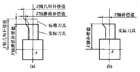
Figure 1 Tool position compensation
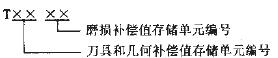
Since there are two forms of offset, the tool position compensation uses two methods. One method is to set the geometric compensation value and the wear compensation value to the storage unit to store the compensation value. The format is:
Another method is to combine the geometric offset and the wear offset to compensate, as shown in Figure (b), the format is:
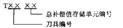
The total compensation value storage unit number has two functions. One function is to select the compensation value corresponding to the tool number and execute the tool position compensation function. The other function is to cancel the position compensation when the storage unit number 00, for example, T0100, indicating elimination + The current compensation value of the tool. Figure 2 shows the effect of position compensation. The solid line in Figure 2 is the programmed trajectory of point A in the center of the tool post. The dashed line is the actual trajectory of point A when performing position compensation, the orientation of the actual trajectory and the compensation value of X and Z axes. Related, its procedures are:
N010 G00 X10 Z-10 T0202;
N020 G01 Z-30;
N030 X20 Z-40 T0200;
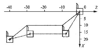
Figure 2 Tool position compensation
The tool structure of the CNC lathe system is shown in Figure 3. In Figure 3, P is the imaginary tool tip, S is the center of the tool arc, r is the tool nose radius, and A is the tool holder reference point.
Figure 3 turning tool structure
Next page
Vat Dyes,Color Dye,Cotton Dyes
Tianjin Zhaobo Chemical Co., Ltd. , http://www.tjaciddyes.com